SerialEM Note: K3 is installed on Talos
- Author:
Chen Xu
- Contact:
- Date_Created:
Oct 25, 2018
- Last_Updated:
Apr 09, 2021
- Abstract
We have upgraded from K2 to K3 on Talos Arctica. Overall, we have had more positive experience than negative one. We are now collecting the first benchmark data, just one week after K3 installation was completed. Of course, we are using SerialEM on it.
I wanted to share our experience here. Hope it helps people to prepare for their own installation.
Installation Went Smooth
The installation was fairly smooth. The engineers had installed K3 at other sites before so they have quite some experience already. Total installation only took three full days. We had two K3 systems in crates - one for Talos and one for Krios. Therefore, one unique advantage we had was an extra set of identical hardware components to swap test when needed.
There were two failed hardware components in the original package for Talos, one was processing board and the other was MIB box and cable. Once these two faulty hardware components were replaced with ones in Krios K3 crates, the system came up nicely.
One can imagine, without spare hardware parts to trial and test, the installation could have taken a lot longer. We were lucky.
SerialEM Control
It was pretty easy to get good control of K3 camera based on previous K2 camera setup. There are only a few things we needed to redo for SerialEM calibration.
Camera Timing and Shutter Dead Time.
Image Shift calibration for all the mags to be used.
Pixelsizes at mag index 4, 16 and 17. They are 46X(LM), 2300X(LM) and 1250X (M). Note: This is only to get SerialEM going, more precise measurement of pixelsize at final image mags will need to be done carefully using different methods, for high resolution image processing.
Stage Shift calibration for mag index 4, 16 and 17. They are 46X(LM), 2300X(LM) and 1250X (M). Double check tilting axis angles from this step too.
The K3 camera section of properties is below:
 1CameraProperties              1
 2Name                          K3
 3K2Type                        3
 4DMGainReferenceName           K3-18140113 Gain Ref. x1.m0.dm4
 5# THESE 5 WILL NEED CHANGING IF CAMERA ORIENTATION CHANGES
 6CameraSizeX                   5760
 7CameraSizeY                   4092
 8SizeCheckSwapped              1
 9RotationAndFlip               0
10DMRotationAndFlip             0
11#UsableArea                   0 0 3712 3840  # top left bottom right!
12UseSocket                     0
13MakesUnsignedImages           1
14XMustBeMultipleOf             4
15YMustBeMultipleOf             2
16FourPortReadout               0
17Binnings                      1 2 3 4 5 6 8
18BasicCorrections              49
19HotPixelsAreImodCoords        1
20#DarkXRayAbsoluteCriterion    20
21#DarkXRaySDCriterion          15
22#DarkXRayRequireBothCriteria  1
23MaximumXRayDiameter           6
24BeamBlankShutter              0
25OnlyOneShutter                1
26StartupDelay                  1.195
27ExtraBeamTime                 0.10
28BuiltInSettling               0.0
29ShutterDeadTime               0.00
30MinimumDriftSettling          0.05
31MinimumBlankedExposure        0.35
32ExtraUnblankTime              0.012
33ExtraOpenShutterTime          0.12
34Retractable                   1
35InsertionDelay                5.0
36RetractionDelay               3.0
37GIF                           0
38Order                         2
39FilmToCameraMagnification     1.31   # orig=1.342
40PixelSizeInMicrons            5.0
41#CountsPerElectron            #37.55 not needed for K3 # measured at 3.15 e/p/s
42ExtraRotation                 0.
43# MagIndex  DeltaRotation (999 not measured)  SolvedRotation (999 not measured)
44# Pixel size (nm, 0 not measured
45RotationAndPixel 3 999 -94.4 0
46RotationAndPixel 16 999 -94.4 1.74   #k2=1.797
47RotationAndPixel 17 999 90.9 3.291   #k2=3.396
48#
49EndCameraProperties
Shutter Control
There are a number of things one should pay attention to, in my opinion. The shutter control is the top 1 on the list.
Shutter control. This is perhaps the most important thing you do not want to miss. If shutter control is not working properly, you might have sample burned without notice. Normally, if shutter control is not working, you will have hard time preparing gain reference. So you might notice it. However, since we are not required to prepare gain reference often in daily bases, if it stops working, you might or might not notice it promptly. You might still get image, but your sample might not be protected as it should be.
With properly working shutter, the beam will get blanked if following conditions are all met:
Hardware components are communicating with each other normally.
DM is running and K3 camera is in inserted position.
Software configuration in DM interface - Camera Configuration has set properly as idle state for shutter one “Pre-specimen” to be closed. There is normally only single shutter cable from Gatan MIB box - shutter 1 connecting to FEI shutter router “CSU” box at one of the channels. This is a BNC connctor. In our case, it connects to Channel C - Blanker. Make sure it is the blanker, as the other one on CSU channel “shutter” means below specimen.
large screen of scope is in raised position (large screen is a switch to trigger sending or retracting 5V signal through the shutter cable.).
In FEI scope “CCD/TV Camera” interface, make sure the fake camera name assigned for K2/K3 (Falcon in our case) is selected from the list and “insert” button is in yellow color. Click on it if this is not. This is to tell FEI CSU shutter router to let Channel C take control electronically, not to mechanically insert K3 camera, as K3 is not fully integrated into FEI TIA system. This is a standalone camera in that sense. In fact, newer version of FEI software no longer requires to add a fake camera onto camera list. Instead, there is a large button “Standalone Camera” to be clicked to do the same.
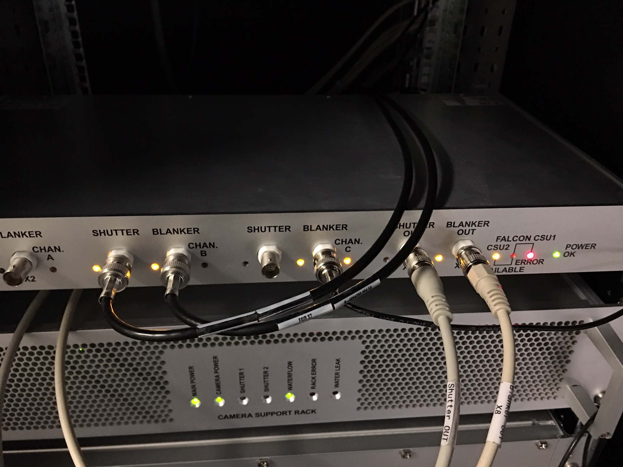
In our case, when all above conditions are met, the green LED “shutter” indicator on K3 power supply unit should be on. The “Blanker” orange color LED indicator on Channel C will be lit when idle. It blinks when a shot is taken from DM or SerialEM. If you take an exposure for 3 seconds, the LED will disappear for 3 seconds. The two images below show Gatan Power Supply unit and FEI CSU unit:
Fig.1 Gatan K3 Camera Power Supply Unit (click for full size image)
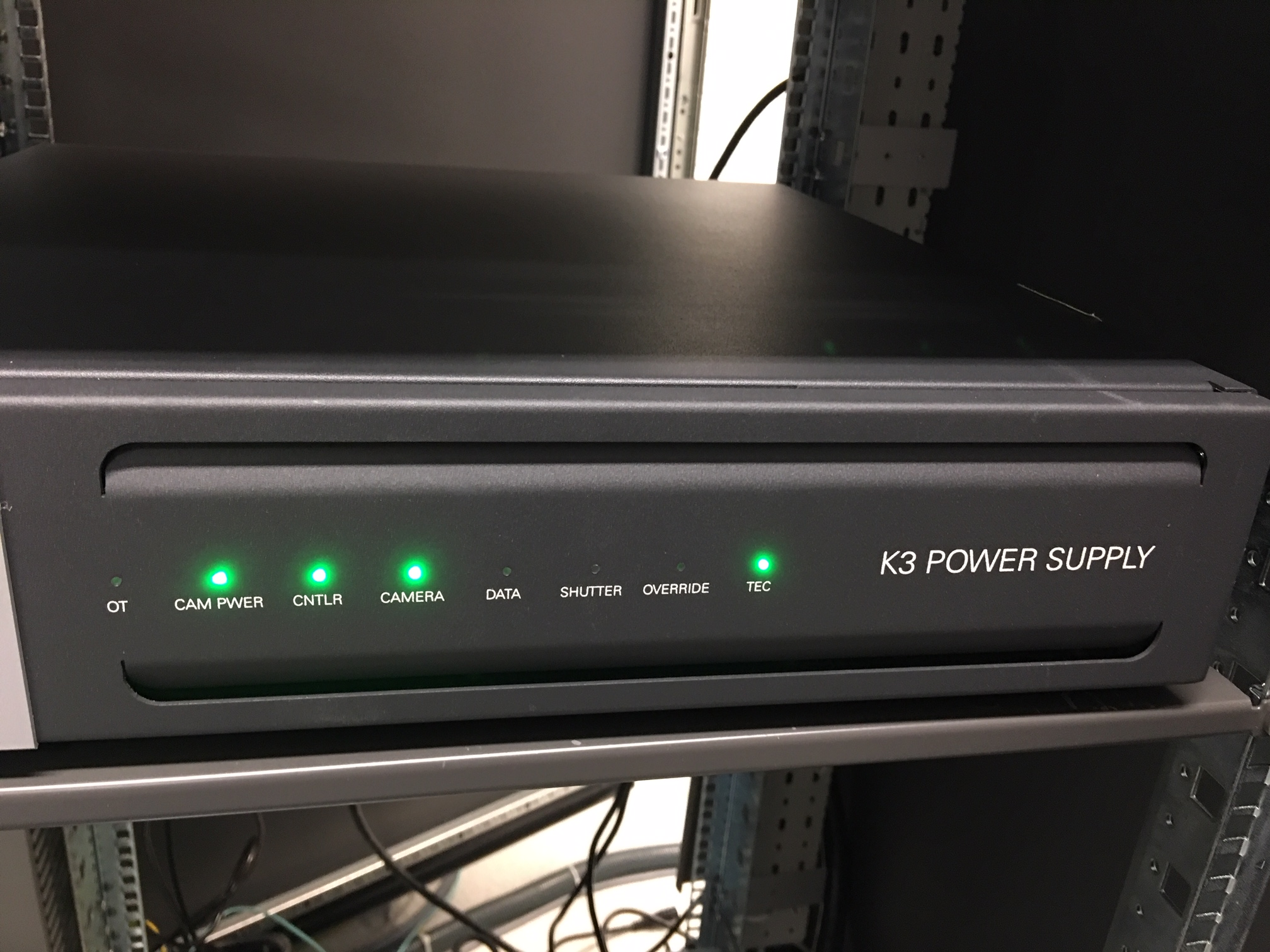
Fig.2 FEI Shutter Router Unit (CSU) (click for full size image)
Please note: at least in our case, during an exposure, there is nothing change to reflect shutter status from either CCD/TV camera interface or FEI’s Jave program “Shutter Blanker Monitor”. This is probably due to Gatan camera being an “external” camera.
To make absolutely sure the shutter is working properly, it is better to check it with burn marker method. You lift large screen and wait for sometime and take an image of ice sample or plastic sample in a lower mag, and you check if you see any sign of burn marker. If no burn marker seen, that would indicate the beam is blanked without a shot is taken.
Other things to Watch
I listed a few more other things here that I also paid attention to.
Camera mounting orientation. This is not critical but can give you an easier life later. Our camera is mounted in the way that camera insertion is toward autoloader. Then there is no need to configure camera rotation and flip in DM configuration.
There is no exsiting fiber NIC available (like the Spare port on K2 computer) for us to use. However, there is a Ethernet NIC on the motherboard you can use. I prefer to have fiber NIC for faster data transfer so I added one PCI-E 8X 10GbE netword card into the main computer. It sits in the very first PCI-E slot from the top. I literually get ~1GB/s real data transfer speed, from SSD Raid X drive to my storage via CIFS. Reverse direction - from storage to local SSD is about 600+ MB/s.
I pre-odered extended 40 meter long data cable bundle, that includes 5 fiber bundles and one Cat6 cable. It also needs a long USB cable to connect to FEI computer for COM port communication for remoteTEM running on FEI scope for scope function calls. This one is easy to miss. I am using remote KVM system for the USB signal. The one we bought is this one, it does support 4k resolution, but refreshing frequency drops to 30Hz.
Only at starting computer, we hear huge jet engine kind of laud sounds. After it is running, it is still noisy not too bad. I heard some lab were testing to use soundproof rack to host the computer. If this is no concern for vibration, then it would be better to locate the K3 computer and soundproof rack in the scope room. I would like that a lot. Not sure how much more heat load this one gives compared to previously K2 computer plus its processors though. I have a feeling that this soundproof server rack should work - https://www.rackmountsolutions.net/12u-ucoustic-soundproof-server-rack/, but haven’t tested anything myself yet. Hope to hear from people about their experience.
There is Nvidia card K2200 for monitor display. That one doesn’t have HDMI port, only two DisplayPort ports. If you need to buy KVM for remote AV/USB purpose, make sure to buy the unit that supports DisplayPort directly. DP to HDMI converter might not give 4K resolution that 32 inch Dell 4K monitor offers.
You should check water flow and air pressure gauge often for a fresh installation of K3, as they might change a bit in the beginning. We had a startup hiccup when the water is a little too low (~19 GPM). It became fine after it was raised to 24 GPM.
If there is any memory test error on any of the processors, one should shutdown and restart computer rather than a software reboot. Power cycle is likely needed to clear out memory errors.
K3 outputs more data than K2, one has to deal with storage capacity seriously if you run a scope effciently. Otherwise, one might find that you quickly run out of data storage space. Saving frame data with compression and without gain applied has clear advantages here!
Our K3 system package came with a GP100 Nvidia card. Also there is MotionCor2 utility via DM interface. However, there is no way to access to MotionCor2 outside of DM. Fortunitely, we can still utilize the powerful GPU card. If we run framewatcher to align ~30-40 Super-res frames, it can do as fast as ~10 seconds for one stack. This is sufficient at least for our session monitoring purpose. Very nice indeed!
Always remember to retract K3 camera first BEFORE you try to insert Ceta camera.
Sometimes on our system, when restarting DM, the communication between DM and microscope gets interrupted. A Keyspan USB Serial Adapter is used to establish the communication in our case. Unplugging and replugging the USB connection usually fixes the problem. However, it it almost impossible to do it remotely. We have found a workaround to re-activate the Keyspan USB Serial Adapter, remotely. 1) Exit DM first, 2) From Device Manager, find “Kayspan USB Serial Adapter”, in its “Driver” tab, disable and enable it. This will reset the adapter. 3) Restarting DM. After that, communication will be OK.
After configuring communication between
DMandRemote TEMserverusing TCP/IP protocol, it has never got interrupted like before. So we abandoned the Keyspan USB apatper completely.
Additional Info
There is some additional information regarding the K3 camera from UTSW facility that you might find useful. Please find the pdf file.