SerialEM Note: Define Image Shift Vectors for Multiple Exposure
- Author:
Chen Xu
- Contact:
- Date Created:
Sept. 27, 2023
- Last Updated:
Oct. 22, 2023
- Abstract
Finding image shift vectors is among the most common tasks for high-throughput multiple exposure setup.
In this note, I try to give some “under the hood” information about the procedure and some new features implemented in the latest versions that makes this easier and more dynamic for our daily operation and potentially automation too.
This is for regular pattern and on a rectangular geometry grid.
The Manual Way
In high-throughput, multiple exposure data collection using image shift on a regular pattern grid, it is essential to have accurate image shift pattern setup so that the beam can go to each and every hole accurately. SerialEM does this from determining image shift vectors from 4 corner hole positions. It uses the IS values for 4 corner poisitions and derive to obtain a pair of basic image shift vectors for current conditions. Also, once these basic two image shift vectors are determined, you can swith the pattern, say from 3 x 3 to 5 x 5 etc without needing to redo this steup procedure.
I suppose you probably are already familiar with the setup in manual way. In a brief summary, the steps are:
Define 3 x 3 (or similar) regular pattern from Multiple Record Setup dialog window.
Add four corner points in an image in circular fashion.
Click on button [ For Corners of Regular Pattern ], and use buttons [ IS to Nav Pt ] and [ Save Image Shift ] to shift to each corner point and save it.
You likely will need to take a Record shot ( e.g. LD R ) to touch up the shift positions before saving them. The figure below shows adjustment before saving the image shift value for that corner point.
Fig.1 Adjusted to Center before saving
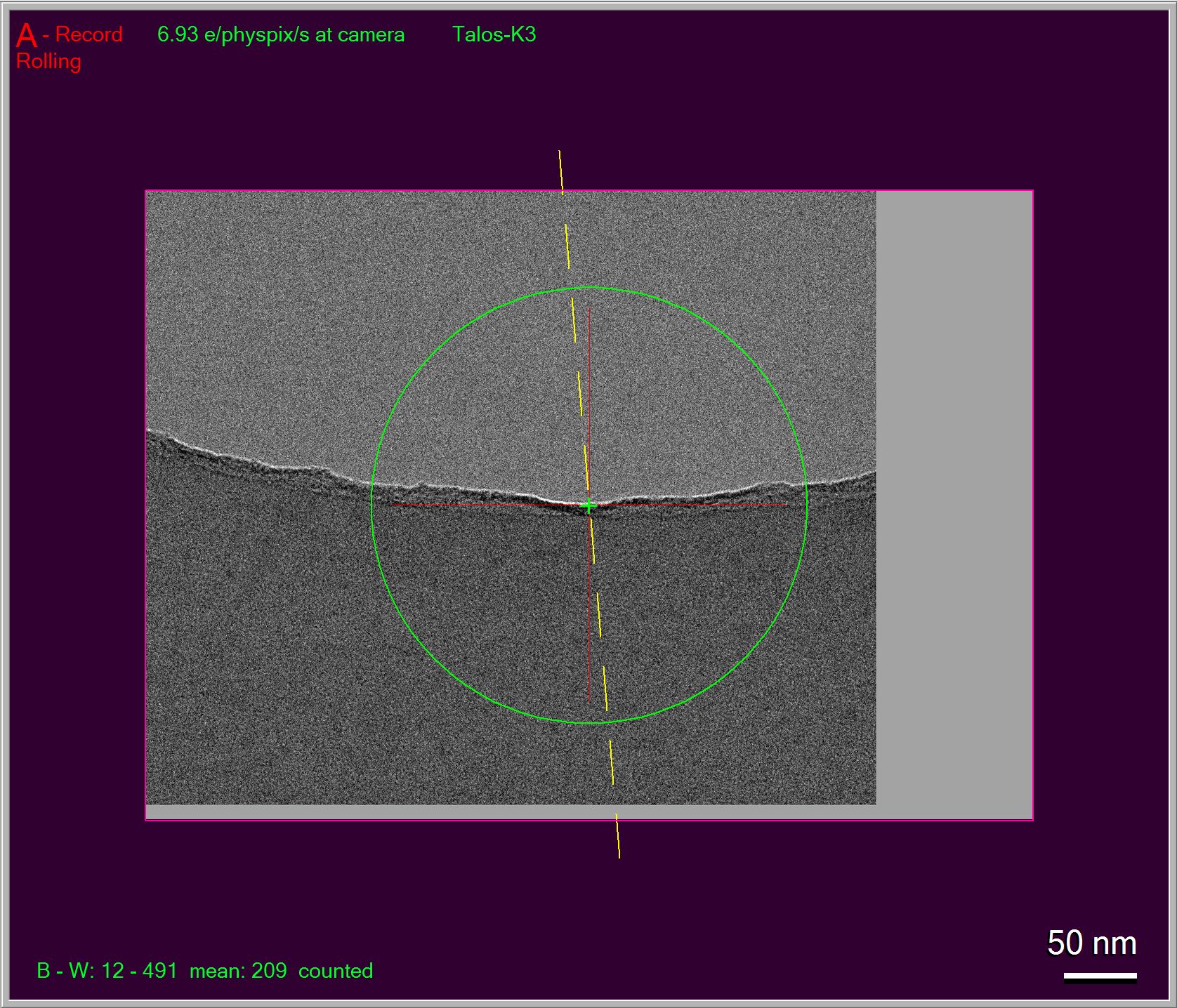
Sometimes, you cannot see feature (such as a edge of partial hole) because the position is too far away in the high mag image. In an ideal world, the image shift in R mag should land on the exact location of the point you picked. But in reality, possibly due to imperfection of system calibrations, this rarely happens. You usually have to reduce R mag temporarily or use an IS montage at R to catch the feature, and you have to do this four times for each of the four corner points.
Admittedly, it is a pain, at least not very fun to me.
Despite the pain, at end of the procedure from the above steps, the precise image shift vectors are obtained. The image shift pattern based on the vectors drawn back to lower mag image (e.g. LD View) might seem off a little, as shown in Fig 5(Q) below. This is again due to imperfect calibrations so showing not being accurate. No worries, in your final collected images, the positions will be right!
As soon as the procedure is finished, there appears a line right under “Regular array of holes” in the dialog window, something like Spacing 2.74 and 2.75um Maximum shift: 3.9um. This indicates that the basic IS vectors for multiple exposure are available or updated. If you have never done this before, this line is not shown until you have done it. If you save setting file, there will be a line starting with “MultiShotParams” containing this very information. And in your next SerialEM session with a new grid, this information will be existed there but likely wrong. You will have to redo this for a new grid.
Oh, you probably will naturally ask: “Can we do this an easier way?” The answer is YES.
Using Hole Vectors
Instead of manually adding some corner points as nav items, we can directly use hole vectors. If we perform hole finding on an image with multiple holes, the hole vectors become available. These are two basic vectors to reflect hole distances in two directions and their relative orientation to the camera system. Even there might not be good holes to be included, the vectors themselves are available after hole finding. They can be used to convert to Image Shift vectors as starting point. We can do this simply by pressing the button [ Use Last Hole Vectors ].
Fig.2 Use Last Hole Vector
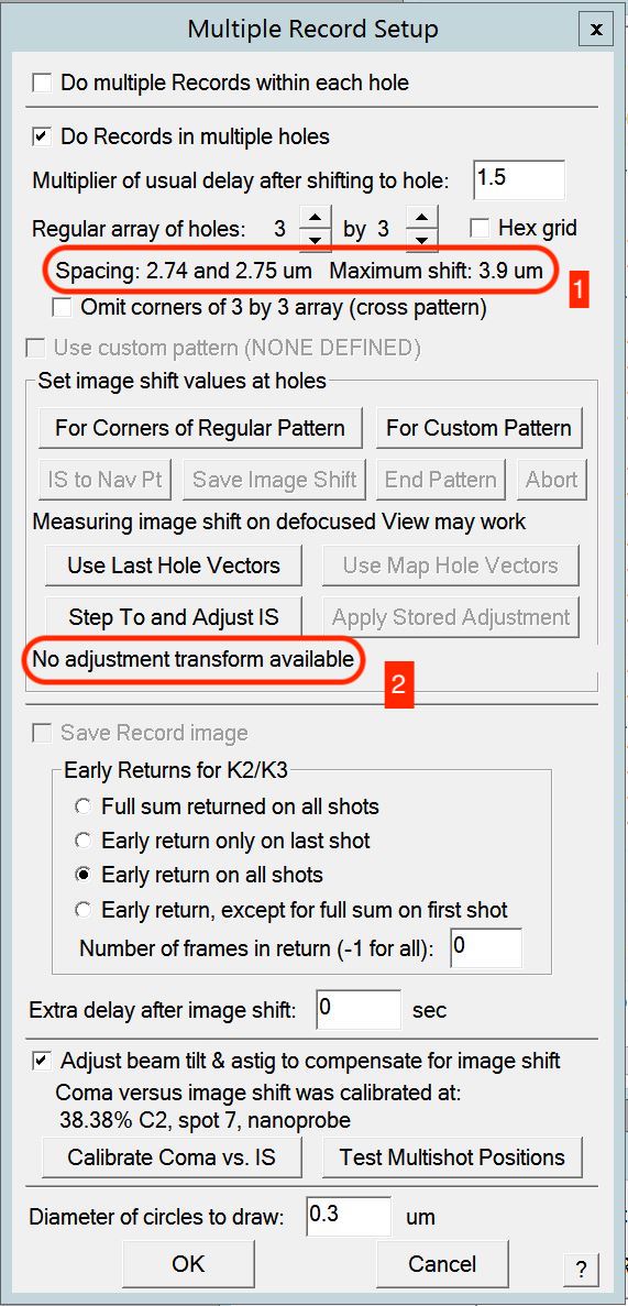
Figure 2. shows two places get updated in the dialog after pushing [ Use Last Hole Vectors ]. Shown in red outline 1, the image shift vectors are updated from the new stage hole vector conversion. And also there is an interesting line “No adjustment transform available” in red outline 2. What is that then?
Adjustment Transform
After the button pushed, we have image shift vectors. And we wanted to refine them by stepping to and adjust so they can be accurate. This is very much similar to previously manual shift, but we do this via a more automatic way from [ StepTo and Adjust IS] button.
Below Figure 3. is a setup dialog from pushing [ StepTo and Adjust IS ] button.
Fig.3 Step and Adjust IS Setup
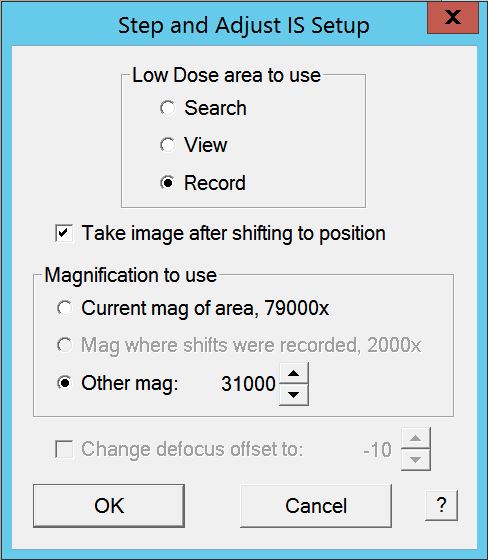
It can conveniently shift to a corner and take a shot for you to see, you can adjust the position and save the image shift value, for this corner, by pressing [ Save Image Shift ] like before. This routine steps through all four points for you. In the end, you have a new set of accurate image shift vectors!
We started with a set of image shift vectors converted from stage hole vectors initially (at LD View mag), and we ended up with final accurate set of image shift vectors (at LD R mag)! This procedure not only determines refined image shift vectors for R mag, but also results in an adjustment transform matrix between the two!
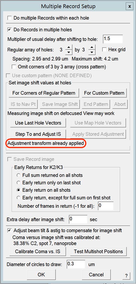
As soon as the procedure is finished, the adjustment transform is available (in memory), and already applied for the CURRENT one, as shown in below figure 4.
Fig.4 Adjustment transform already applied
Below is the figure 5 showing 3 x 3 patterns before and after this adjustment transform.
Fig.5 Image Shift Patters before and after adjustment
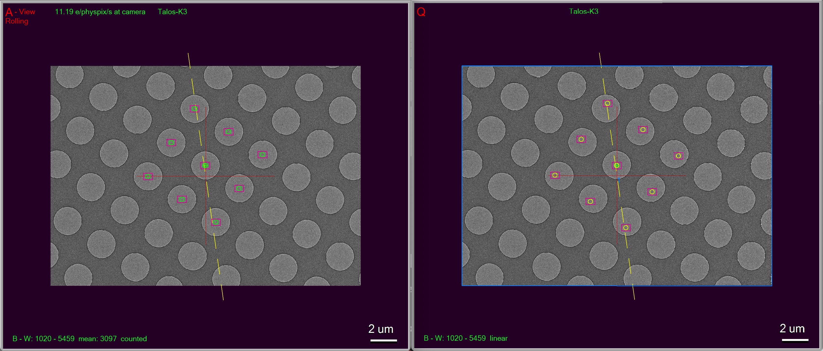
The left image 5.(A) shows image shift pattern right after converted from stage hole vectors. The right one 5.(Q) is the pattern after adjustment is done. Note, the beam circles in the image (A) is in green, and they become yellow after adjustment. You may also notice the pattern after adjustment seems shown slightly off from hole positions.This is due to imperfection in calibrations. In ideal world, the two would be lined up perfectly. Here, the off-looking one is actually an accurate set.
A Smarter and More Automated Way
The adjustment transform matrix is also preserved in setting file.
HoleAdjustXform 20 0 0 20 34 1.009630 0.005789 -0.002779 1.021203
It is a matrix between LD View (index 20) and LD R(index 34). As long as your LD View and LD R conditions doesn’t change much, this matrix works conveniently. When you start with a new grid, your old pattern is no longer valid, but this adjustment transform stays good.
So for daily operation, you find hole on the new grid first and you then [ Use Last Hole Vectors ]. As soon as that button is pushed, the message to tell you the transform is available shows up, as shown in red outline below.
Fig.6 Adjustment transform available
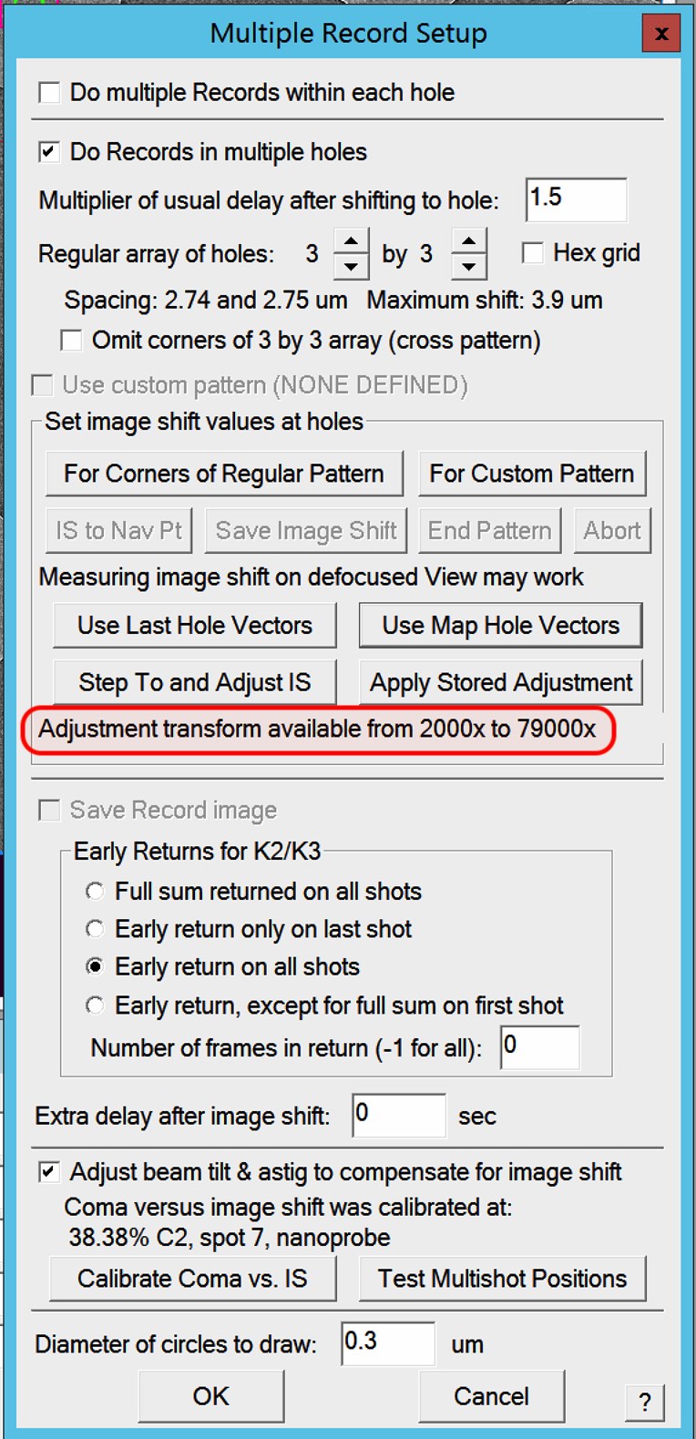
You can utilize the transform by pushing the button [ Apply Stored Adjustment ], your new Image Shift vectors for the pattern is updated immediately. You might want to do [ StepTo and Adjust IS ] here also to refine the IS vectors for today’s condition and make sure the positions are perfect. This time, not like manaully adjusting from scratch, you will find your features easily.
It is worth mentioning that if you perform hole finding on a montage map overview image, the map item will contain the hole vectors information. If you save the nav file and open it in text editor, you can see the two lines:
HoleISXspacing = 2.69895 -0.758684 0
HoleISYspacing = -0.768892 -2.71193 0
You can then click on [ Use Map Hole Vectors ] on a map item and then [ Apply Stored Adjustment ]. As you can imagine, this can work for a grid with slight geometry change across the grid meshes. It can also be used conveniently to a new grid with completely different geometry.
Once your adjustment transform is good, you can do it in script too, to have an automated workflow.
UseHoleVectorsForMulti 0    # 0 means LD Record mag
AdjustMultishotPattern 0